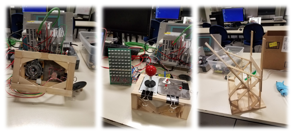
One of the most fun and interesting projects that I’ve worked on during undergraduate was for a mechatronic class where I and my team designed and built and arcade game machine from scratch. The project inspiration started with the extra LED lights leftover from the midterm project. Our team wanted to exploit the power of LEDs and utilize them for the final. Many different ideas were considered, and we initially settled on a TV screen. The TV screen can be used for displaying animations and music videos, but the idea of a video game was enticing. Combining the two concepts, we started to work on wiring the LEDs to a prototype PCB. As the screen was being made, the idea of developing an Arcade cabinet to turn the TV screen into an Arcade machine inspired the team and this became our final project proposal. I was responsible for building the Pacman game and assisted with electrical wiring as well as programming music. Below is an embedded Youtube video of our final product.
Arcade Cabinet Construction and Design Functionality
The Arcade Cabinet was designed to mimic the functionality of a real video arcade machine. Functionality includes ergonomic joypad, ease of access for maintenance, glare shroud, electrical inner storage, and aesthetics. The main materials of the cabinet include popsicle sticks, hot glue, foam poster board, felt padding, a cup holder, and Rubbermaid plastic.
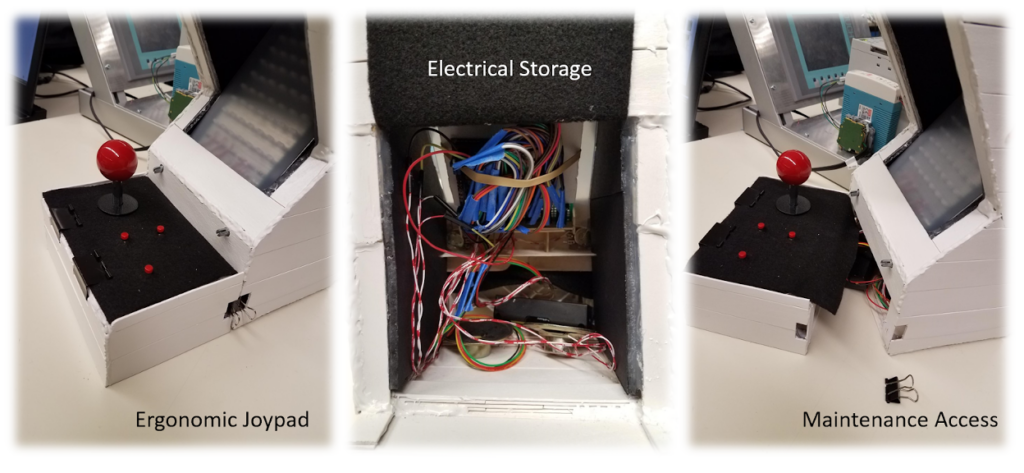
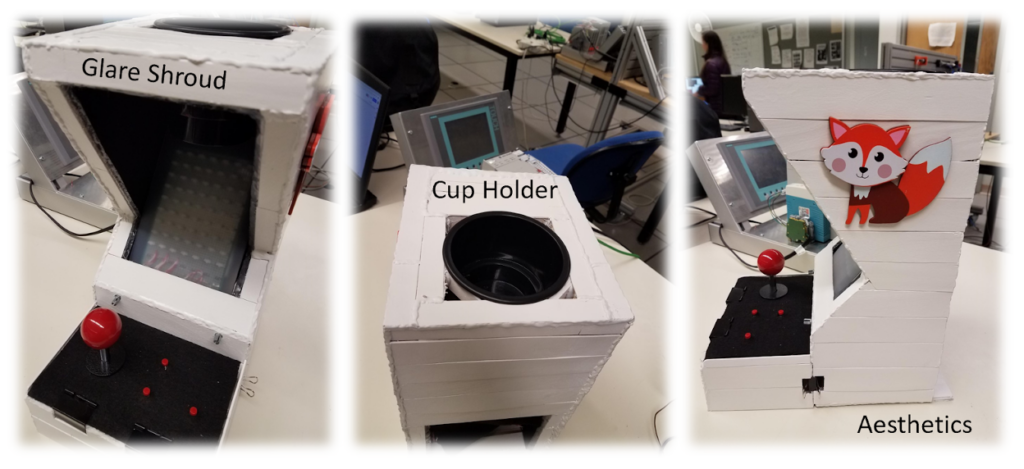
The ergonomic joypad was covered in felt padding for comfort and was designed to be separate from the main cabinet to provide ease of access for maintenance. The maintenance access is essential for wire assembly and troubleshooting. The joystick and button wires feed under the joypad and into the electrical inner storage area, which is located at the base of the arcade cabinet. The electrical storage area is home to all the wires connecting to the uc32 microcontroller board. It is also home to a dual battery power source and twin speakers. A fun highlight of the team’s arcade machine is a cup holder for the user’s beverage. The cupholder is located on top of the cabinet, which sets just above the video screen.
Electrical Design
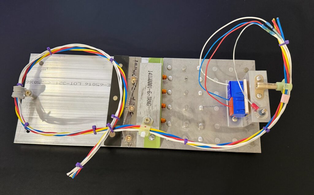
Wiring Diagram
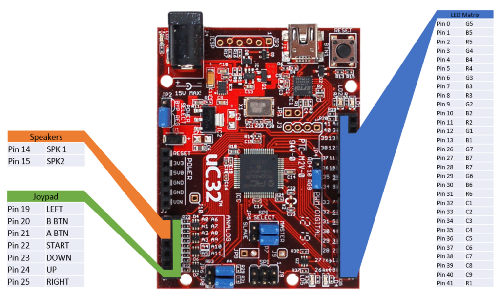
The size of the LED matrix was determined by the number of I/O pins available on the uC32, using all the pins on the right side and leaving the left side open for other devices. The arcade machine uses all but 3 I/O pins available.
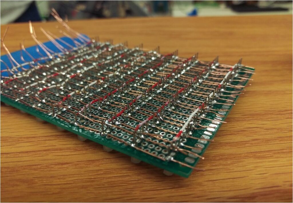
All wiring and routing is done on the prototype PCB, this eliminates the need for a breadboard and creates a more compact design, male and female headers are used to make connecting the prototype PCB to all other components easy and organized.
LED Matrix
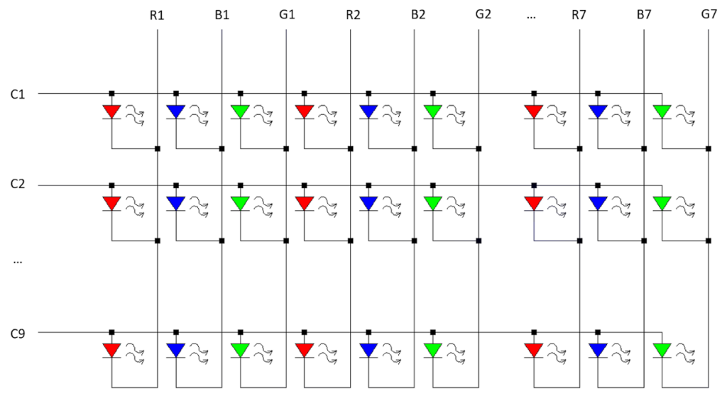
The common anode RGB LEDs are wired in a matrix as depicted above. This method allows us to control 189 individual LEDs using only 30 pins. To turn on an LED, the desired row (C1-C9) is set to HIGH and the desired colors are set to LOW. while it’s possible to set the entire row at once, each LED is scanned individually as the uC32 cannot supply enough power for multiple LEDs at once without losing color accuracy.
Joypad
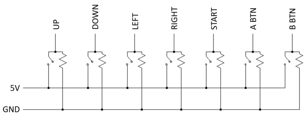
The joypad is a simple input device consisting of a joystick and 3 separate momentary switches. Though it would have been possible to wire the buttons in a matrix to use less pins, the increased complexity was not worth opening a single pin. All inputs are digital and pulled down to ground when not activated and can be used simultaneously.
Speakers
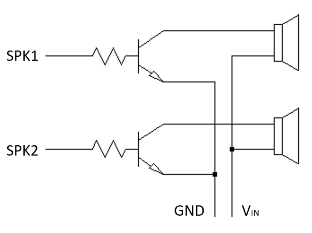
The speakers were originally connected directly to the uC32 and ground. Due to the low but audible sound, a transistor was implemented to amplify the signal. In addition, potentiometers were added before the amplifier to control the volume of each speaker individually. Though it would have been possible to use the DAC on the uC32 for more sophisticated control of the speakers, however, the simpler control method suited the needs for the project.
Featured Games
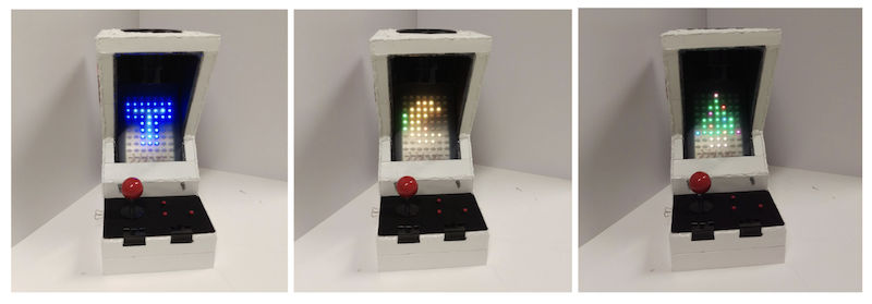
The Arcade machine menu is a selection of games consisting of Tetris and Pacman. The Tetris game is played with two push buttons and the joystick. The push buttons are used to change the block orientation and the joystick allows the block to be moved left, right, up and down the screen. There is no level up in the game. However, the game difficulty increases with each additional line completed. The Pacman game utilizes only the joystick as physical input. The user can move Pacman in four directions, left, right, up and down the maze. The game has four main built-in levels with increasing difficulty in the maze pattern and in the ghosts’ speed. From the main menu, the user can also listen to Jingle Bell while watching the colored Christmas tree being displayed on the screen.