In the past couple weeks, I attended another training session at work on Geometric Dimensioning and Tolerancing (GD&T).
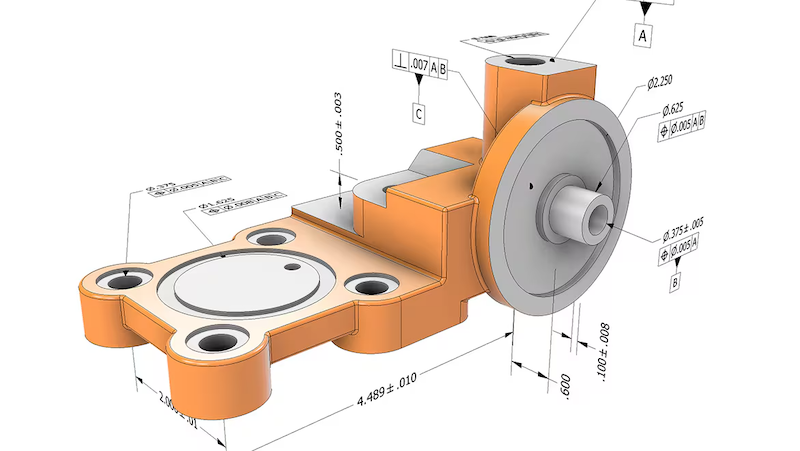
GD&T is a symbolic language used in engineering drawings to define and communicate tolerances or allowable variations in a part. GD&T is governed by ASME Y14.5 standard and is widely used in industries requiring high-precision components such as aerospace and automotive.
GD&T is a topic that I had briefly learned about in my undergraduate curriculum but had never had the proper training to fully understand the tool. In my early career, it was discouraged to use GD&T in my engineering because it tends to increase the cost of the parts due to high inspection requirements. However, if use correctly, GD&T can reduce the total manufacturing costs by removing ambiguity in the interpretation of design intent, improve assembly fit by allowing functional tolerances and reduce scrap rate. It provides a way for companies to control the quality of parts received from the suppliers and prevents disputes that might lead to increase in procurement cost.
GD&T History
The concept of GD&T was developed by Stanley Parker, an engineer at the Royal Torpedo Factory in Scotland during World War II. He observed wartime production issue where many parts were being rejected due to imperfect measurements. Even in cases where the discrepancy is small, the parts still fail to meet functional requirements. Parker then came up with the concept of true position (the theoretical exact location of a feature on a part) and tolerance zone (the specific 3D space or boundary that constrain the variation of a feature). In 1940s, the U.S. military developed the first standards for GD&T, MIL-STD-8. In 1982, the American Society of Mechanical Engineers (ASME) released the Y14.5 standard, which inherited and modernized those principles established from the original MIL-STD-8. The latest revision of ASME Y14.5 standard was released in 2018.
GD&T Feature Control Frame
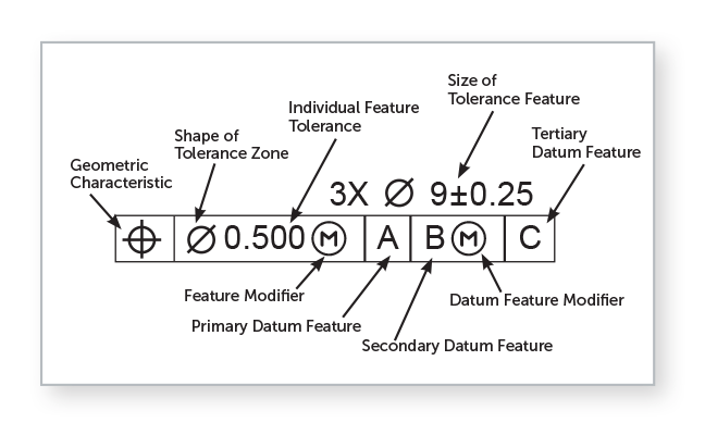
The GD&T feature control frame is used to specify the tolerance values acceptable for a feature of a part. The tolerance value is the difference between the minimum and maximum dimension limits. For example, in the image above, the size of the feature is specified using a diameter symbol with a value 9 and a tolerance zone of plus or minus 0.25. The feature modifier Ⓜ is used to define additional tolerance of 0.500 at maximum material condition (smallest hole or largest pin). The feature is inspected relative to datum features A, B and C (a physical surface or an edge used as a physical contact point for inspection equipment) in order of importance, primary, secondary and tertiary datums.
GD&T Pros and Cons
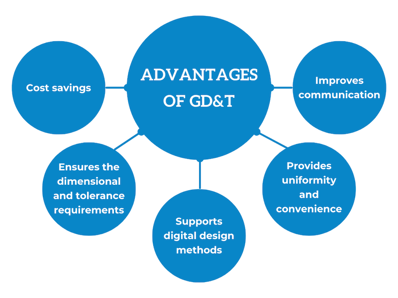
GD&T provides a clear and complete way to communicate part design intent. It is universally interpretable, meaning that it can be understood in the same by all engineers, suppliers, manufacturers and quality inspectors. GD&T maximizes manufacturer’s freedom and thereby reduces costs.
One disadvantage of GD&T is that it adds complexity to the drawings during design and review. The language might not be interpret and understood correctly by all manufacturers if not property trained.
References
“GD&T Basics – A Comprehensive Introduction to Geometric Dimensioning and Tolerancing.” Five Flute, www.fiveflute.com/guide/gd-t-basics-a-comprehensive-introduction-to-geometric-dimensioning-and-tolerancing/. Accessed 7 Mar. 2026.
“Geometric Dimensioning and Tolerancing (GD&T) in Design and Manufacturing.” Autodesk, www.autodesk.com/solutions/geometric-dimensioning-and-tolerancing. Accessed 7 Mar. 2026.
Lindenberger, Chris A. “Definition of Terms- Tolerance Zones.” Metalcraft, 11 Nov. 2018, metalcraftind.com/definition-of-terms-tolerance-zones/.
“Precision Edge: Bilateral & Unilateral Tolerance.” EZIIL, eziil.com/tolerance-types/. Accessed 7 Mar. 2026.
Willson, David, et al. “GD&T 101: Our Guide to Geometric Dimensioning and Tolerancing.” Fictiv, www.fictiv.com/articles/gdt-101-an-introduction-to-geometric-dimensioning-and-tolerancing. Accessed 7 Mar. 2026.